3d Printing News — Large Scale 3D Printing - Cosine

Colby Cupit

Software Testing Environment

To help catch errors earlier and prevent them from making it to the user, we proposed the creation of a testing environment at Cosine’s facility in Houston. The idea behind it being that any time we make a change to our software, we run a suite of tests and the software is not released to the user unless all of those tests pass.


We use a software called Jenkins in order to create this testing environment. Jenkins is what is known as an automation sever. Cosine has been using Jenkins for quite some time as a build server to compile our software and produce installable files. Now we are using it as a testing environment as well. Another technology that Cosine has already been using but was very instrumental in allowing us to develop this testing environment is Virtual Machines. A Virtual Machine is a digital representation of a physical computer and we use them in many different ways, but we were able to utilize them in the testing environment by creating a virtual machine for every physical printer we have. Then on each virtual machine we have what is called a Simulator. This is a piece of technology that is part of the Motion Control system that allows us to have a simulation of a physical printer, so we can do things like start a print and it will load the print like normal and the “axes” will move without anything happening physically.


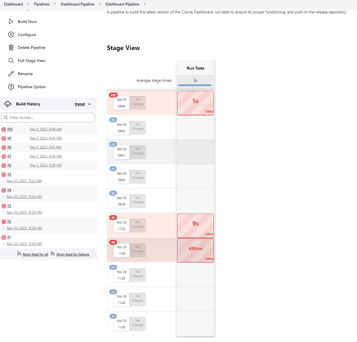
The workflow of the testing environment is that someone commits their code to our version control system (SVN), and then that code is built on Jenkins. If the code builds correctly then it is used in what is called a Pipeline on Jenkins . A pipeline consists of a series of stages that the software has to pass before it can be released to a customer. If the software fails a stage then we determine why it failed and fix it, and then iterate upon this process until it passes all of the stages. Building the executable, installing it on a virtual machine, and running a print on a virtual machine are all examples of different stages of a pipeline. In the future we will also have a test to run the software on a physical printer as well.


The creation of this testing environment has greatly reduced the number of bugs that have been able to reach customers which in turn has saved both Cosine and it’s users countless hours of time figuring out and fixing bugs. As with any software project there are still bugs that make it through, but as we find new bugs we create more tests and there are fewer and fewer bugs that find their way to the end user.

Enhanced Debugging Tools

Here at Cosine, we have a diverse array of customers from different industries. More often than not, we have found that our customers do not want their printer to be connected to the internet because of security or intellectual property (IP) concerns. This presents a problem for us when it comes time to troubleshoot issues because remoting into the printer and diagnosing the problem is not possible. We instead have to tell the customers what files to email to us.

To help account for this issue, we created what we call Enhanced Debugging Tools. These tools are used in a couple of different spots in our software. The first being the Export Error Logs button. All this button does is create a zip file of the two error logs (one for the Dashboard and one for the CosineAdditiveService). This is a very simple but valuable tool because half the time when an issue occurs, it is caught and logged in one of those error logs. Another tool is the ability to export information surrounding a specific print. When print issues occur, we have customers send over the post processed print file to help us determine the cause of the problem. To simplify this process, we created a checkbox in the Print History tab and a corresponding button in that tab, so the customer can select which prints they are having trouble with and then hit the button to export the information. There are a couple of different things that get exported during this process. The first is the post-processed print file, as mentioned before. Second is the truncated error logs that only contain errors that occurred during the time that the print was running. Finally, information about the selected material and a log of all database communication during the time the print was running. As mentioned before, some customers have IP or security concerns, which means that sometimes they cannot send us the actual print they are having trouble with. We have accounted for this as well by having a popup when they go to export the prints that asks if they want to include geometry or not. If they don’t want to include geometry (which is essentially the main part of the print) then the outputted file would just contain the header comments which shows us things like what slicer and machine settings they are using.

The combination of these tools helps immensely in cutting down the time it takes to troubleshoot an issue. Previously, the manual process for collecting information from offline printers was tedious and prone to error. These new tools help automate that process and decrease our turnaround time when resolving issues. Here at Cosine, we strive to provide a quality service for a quality product, and this is just one more step towards that goal.

Advanced Work Coordinate Systems

We wanted to highlight some of our new features in the blog, one of which is the Advanced/Extended Work Coordinates System.

If you have a background in the CNC world, then you will be well acquainted with Work Coordinate Systems, and if you are familiar with Cosine’s machines, then you know that we have been utilizing Work Coordinate Systems already. For the uninitiated, I will provide a brief overview.

A Work Coordinate System is essentially a reference point for the origin of a machine. If we change the Work Coordinate System, we change where the origin is. Changing the origin allows us to move where on the bed a part is printed. This is helpful in many situations, one of which is that you just finished a print on one section of the bed, and you want to print the same thing but on a different section of the bed. Instead of reslicing the print so that it is moved to the different part on the bed, you would just change your Work Coordinate System and then proceed with your print.

So that is a brief overview of what a Work Coordinate System (or WCS) is. Now we will discuss what we call Advanced Work Coordinate Systems.

When we previously used WCSs, we would have only a single WCS that would be overwritten upon each change. Now we can choose from up to 9 different WCSs, that we can modify individually to fit our needs. The 0 index WCS is what is known as the Machine Coordinate System because it cannot be edited by the user, and it always has offsets of 0. Also, as mentioned previously, we were able to only change the offsets for the X, Y, and Z. With the new Advanced Work Coordinate Systems, we can now also change the offsets for the A, B, and C axes (only relevant for machines that have those extra axes), as well as the Yaw, Pitch, and Roll.

The offsets for the Pitch, Yaw, and Roll offsets enable us to do more things that we previously were not able to. When these offsets are changed (their units are degrees), you can rotate around the X, Y, and Z axes by the degree offset that you set. This allows us to do things such as align the coordinate system to an object that you are printing on or to account for some error in the print surface we are printing on, such as if the print surface is misaligned in the y axis all without having to modify the g-code we are printing.

Advanced Work Coordinate Systems open up many more printing possibilities and we are excited to see how our customers end up using this feature!

Web Analytics